

Turning an output on and off with the same momentary pushbutton using ladder logic is trickier than it sounds. This article will show how to implement flip flop logic for CLICK PLCs from AutomationDirect*, but it can be applied to any PLC.
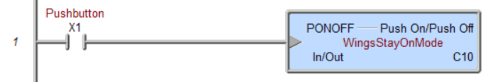
Some PLCs have dedicated instructions for this purpose. For example, if you’re using a PLC in the Do-more series, such as a BRX, take a look at the PONOFF instruction.
But if you’re using a CLICK PLC, flip flop logic, also referred to as toggle logic, is what you need.
Flip Flop Ladder Logic
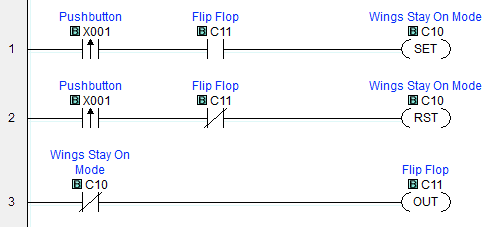
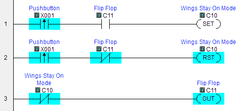
In the CLICK Programming Software, the ladder logic for our flip flop example looks like this:
How it works
First, a few notes.
The first contacts in both rungs 1 and 2 are rising edge contacts for our pushbutton input X001. Edge contacts are only on for one scan of the program. Rising edge contacts are on for the scan where the bit changes from OFF to ON. Insert rising edge contacts in the CLICK programming software with the toolbar icon or Shift+F2.
SET and RST (Reset) instructions turn the internal relay bit C10 on and off respectively. A set bit remains on until reset, regardless of the status of the contacts in the rung that initially turned it on. “Set” and “reset” correspond to “latch” and “unlatch” in other PLC brands.
As the program runs, the PLC scans the rungs, top to bottom, left to right, over and over.
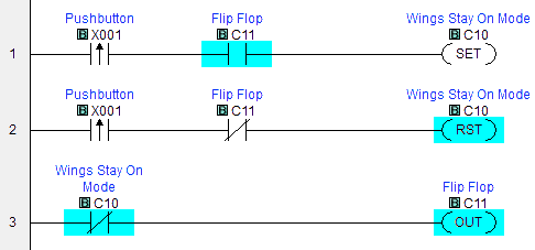
In the following screenshots, contacts that are passing logical “power” are highlighted in cyan, along with active output states. When the path from the left rail to the output consists of all highlighted contacts, the output instruction executes.
Initial state
When the system is first powered on, internal relay bits like C10 and C11 are OFF unless they have been configured to be retentive. Let’s also say that nobody is pressing the pushbutton at power-up, so X001 is OFF as well.

The PLC scans the rungs.
Rung 1 – The pushbutton, X001, is OFF, so no “power” gets to the output instruction of rung 1 and C10 remains OFF
Rung 2 – X001 is OFF. Again, no “power” gets to the output instruction of rung 1.
Rung 3 – C10 is OFF, so the normally closed contact allows power to pass and turn C11, our flip flop bit, ON.
The PLC continues to scan the program, but unless the state of any contacts in the rungs changes, none of the outputs in our logic change state.
First button press
Now let’s say at the Big Ol’ Jet Airliner factory that the Wing Attachment Department attaches the wings and presses the X001 pushbutton.
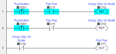
Rung 1 – The rising edge contact for X001 is ON for the scan of the program where it transitions from OFF to ON. Flip flop bit C11 was turned on during a previous scan. So C10, Wings Stay On Mode, is set ON.
Rung 2 – As with rung 1, X001 is on for this scan. Flip flop bit C11 is ON, so the normally closed contact does not pass power and C10 does not get reset.
Rung 3 – C10, Wings Stay On Mode, was set ON in rung 1, so the normally closed contact opens. This prevents power from reaching the output and C11 goes OFF.
As the pushbutton is held, C10, Wings Stay On Mode, does not get reset in rung 2 because the rising edge contact for X001 does not pass power in scans after its OFF to ON transition (or until the pushbutton is released and pushed again).
When the pushbutton is released, the status of the circuit looks like this:
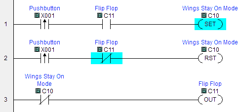
Remember, C10 stays on despite the rung’s logic no longer being true because C10 was SET.
Second button press
If the pushbutton is pressed again, well that can’t be good, can it?
Rung 1 – The rising edge contact for the pushbutton X001 transitions from OFF to ON in this scan, and so allows power to pass. But the flip flop bit C11 is OFF, so the SET instruction does not execute.
Rung 2 – The rising edge contact for the pushbutton X001 is allowing power to pass for this scan. Flip flop bit C11 is OFF, so the normally closed contact allows power to pass. This means the RST instruction for C10 executes, and Wings Stay On Mode turns OFF.
Rung 3 – Wings Stay On Mode is now OFF, so the normally closed contact allows power to pass and turn on the flip flop bit C11.
As the pushbutton is held, the rising edge contacts for the pushbutton X001 do not pass power for subsequent program scans, so none of our flip-flop-related outputs change state.
When the pushbutton is released, the ladder logic looks the same as it did in the initial state.
Well, we can hear alarm klaxons sounding and passengers screaming, so maybe we should try turning Wings Stay On Mode back on…
This article was inspired by The Far Side by Gary Larson.
*CTRLfreak.io is not affiliated with AutomationDirect.


Hello, im noob 🙂