

My panel layouts use 2D symbols for the components. I rarely draw any from scratch since most manufacturers or vendors provide drawings from which the symbols are easily created. Sometimes, however, the provided drawings lack the view or detail I need. For example, the drawings might include a front and side view but no top view. In these cases, I make my own 2D views from the 3D model of the component when available. This article describes a process for quickly and easily making 2D AutoCAD Electrical symbols from 3D models for panel layout.
There are other methods for converting 3D models to 2D views or drawings in AutoCAD, including the FLATTEN and FLATSHOT commands. The process described in this article is just my preference for getting clean views in the orientation I want.
Get the model
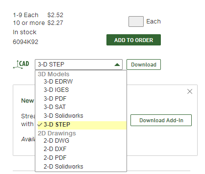
The model file(s) will typically be available in the same area as where you downloaded the 2D drawing. Look for file extensions of .stp, .igs, or .sat. These and other formats are for 3D models.
Import the model
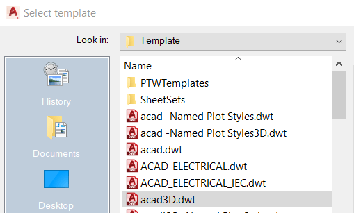
- Enter the NEW command at the AutoCAD command prompt and create a new drawing based on the acad3D.dwt template.
- Enter the IMPORT command at the command prompt.
- On the resulting Import File dialog, set the Files of type field to match the downloaded 3D model file, navigate to the file, and select it. Click Open.
- There will be a pop-up in the lower right of the AutoCAD screen that says “Import File Processing Complete” and includes a link to the file. Click the link.
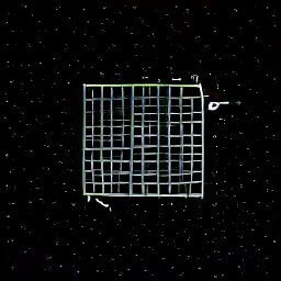
The model may or may not appear in the drawing view. You can Zoom All to confirm it was imported.
Create the 2D view
This is the part you’ve been waiting for.
- Enter the VIEWBASE command at the AutoCAD command prompt.
- At the “Specify model source” prompt, type M for model space and press Enter.
- At the “Select Objects or [Entire Model]” prompt, I typically just press Enter for Entire Model. If the model is of an assembly that you only need part of, you might opt to select objects instead.
- At the “Enter new or existing layout name to make current” prompt, select the desired paper space layout to use. If in doubt, press Enter for Layout1. This will open the Layout1 paper space view of the drawing.
- At the “Specify location of base view or…” prompt, set the desired parameters. For example, I usually enter H for hidden lines which brings up a “Select style” prompt where I enter V for Visible lines (no hidden lines).
- Move the mouse pointer over the layout so you can see the base view’s orientation. You can project other views from this base view, but if you cannot get the desired view from projecting, you can enter O and select a different orientation for the base view. Alternatively, go back to model space and rotate the geometry as necessary then start VIEWBASE again.
- With the desired parameters set, click the point on the layout view where the base view should be inserted.
- You still have a chance to change some options here, or press X to exit. You can project other views in the next step if the base orientation is not the one you need to export.
- To project other views, move the mouse pointer around the layout. When the desired view appears, click to insert it. In some cases it is good to have another view as reference. For example, another view might indicate which way is up in the base view, or the center of the DIN rail slot.
- When finished inserting other views, enter X to exit the VIEWBASE command.
If you don’t like the results, you can go back to the model space and try VIEWBASE again. If you don’t see a way back to model space, enter the LAYOUTTAB command and set it to 1 to make Model, Layout1, Layout2, etc. tabs appear.
This sounds like a lot of steps, but after you’ve been through it a few times it’s not a big deal. And the first steps are typically Enter, Enter, Enter.
Export the layout to a 2D drawing
- With the layout view active (probably Layout1), type EXPORTLAYOUT into the AutoCAD command prompt, and press Enter.
- Choose the destination folder and filename.
- Click Save.
- A pop-up will appear prompting whether or not to open the created file. I typically opt to Open it.
Create the panel layout symbol
This article assumes you know how to create AutoCAD panel layout symbols.
With the exported layout drawing open from the previous section, start AutoCAD Electrical’s Symbol Builder. Make sure to specify that it is a Panel Footprint symbol. Then it is just a matter of copying (CTRL+C) geometry from the exported layout drawing and pasting (CTRL+V) into the Symbol Builder block editor, scaling the geometry if necessary, and adding the required attributes.

I like the valuable information you provide in your articles.
I’ll bookmark your blog and check again here frequently.
I am quite certain I’ll learn a lot of new stuff right here!
Best of luck for the next!
Thank you very much! The articles will be pretty basic and/or quick write-ups as I get used to the platform and create some building blocks for other articles to reference, but I have big plans! You can follow me on Twitter (@CTRLfreak_io) to get notifications of new posts.